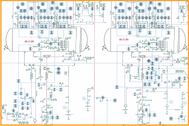
In the world of engineering, especially in industries like oil and gas, chemical processing, and power generation, P&ID (Piping and Instrumentation Diagrams) play a vital role. These diagrams act as the blueprint for designing, maintaining, and troubleshooting complex systems, providing detailed insights into the piping, equipment, and instrumentation required for a process.
In this blog post, we’ll explore what P&IDs are, their significance, key components, and how to effectively read and interpret them. Whether you’re a seasoned professional or new to the industry, understanding P&IDs is essential for efficient project execution.
Piping and Instrumentation Diagrams (P&IDs) are schematic illustrations that detail the relationships between piping, equipment, and instrumentation in a process system. They are used in engineering design to:
P&IDs are commonly created during the early stages of plant design and are used throughout the project lifecycle for operations, maintenance, and upgrades.
Design and Engineering:
Operations and Maintenance:
Safety and Compliance:
A typical P&ID includes:
Each component is represented using standardized symbols defined by organizations like ISO or ANSI.
Start with the Legend:
Follow the Process Flow:
Understand Equipment Tags:
P-101 (Pump 101) or T-202 (Tank 202) help identify specific equipment.Decode Control Loops:
FIC-302) to understand how a parameter like flow is controlled.Standardization Variations:
Complexity:
Updates and Revisions:
Learn More: P&ID symbols
Modern tools have made it easier to create, edit, and annotate P&IDs. Software like eAI provides advanced features for:
Learn more about eAI and how it simplifies P&ID management.
Mastering Piping and Instrumentation Diagrams (P&IDs) is crucial for professionals in process industries. These diagrams not only streamline design and operations but also ensure safety and compliance. Whether you’re designing a new system or troubleshooting an existing one, a solid understanding of P&IDs will enhance your efficiency and effectiveness.
If you’re looking for tools to manage and annotate P&IDs seamlessly, check out eAI. With its intuitive interface and powerful features, eAI is designed to help engineers take their projects to the next level.