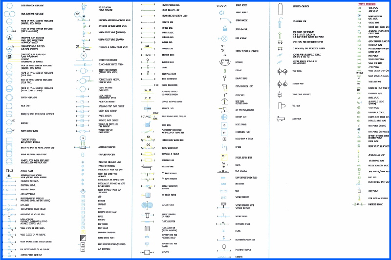
Piping and Instrumentation Diagrams (P&IDs) are the backbone of process engineering, providing a detailed map of how systems and components interact. At the heart of these diagrams are P&ID symbols, which represent equipment, piping, instruments, and controls in a standardized, universally understood format. These symbols act as the “language” of P&IDs, allowing engineers and operators to interpret complex systems at a glance.
In this blog post, we’ll explore the purpose of P&ID symbols, their standardization, and where you can find comprehensive references to these symbols. Whether you’re new to P&IDs or looking to deepen your understanding, this guide will equip you with the basics.
P&ID symbols are graphical representations of the components in a process system. They are used to:
Standardization ensures that P&IDs are universally interpretable, regardless of the industry or region. Common standards include:
Standardized symbols eliminate ambiguity, allowing engineers, operators, and regulators to work together seamlessly.
Equipment Symbols:
Piping Symbols:
Valve Symbols:
| Symbol | Name | Description |
|---|---|---|
 | Diaphragm Actuator | A valve with a diaphragm actuator. |
 | Actuator | A valve with an actuator. |
 | Manual Actuator | A valve with a manual actuator. |
 | Motorized Actuator | A valve with a motorized actuator. |
PI for a pressure indicator.| Symbol | Name | Description |
|---|---|---|
 | Computer Function Control Room | A computer function in the control room. |
 | Computer Function Field | A computer function in the field. |
 | Computer Function Local Panel | A computer function on a local panel. |
 | Control Function Control Room | A control function in the control room. |
 | Control Function Field | A control function in the field. |
 | Control Function Local Panel | A control function on a local panel. |
 | Discrete Instrument Control Room | A discrete instrument in the control room. |
 | Discrete Instrument Field | A discrete instrument in the field. |
 | Discrete Instrument Local Panel | A discrete instrument on a local panel. |
Start with the Legend:
Understand Equipment Tags:
P-101 provide unique identifiers for equipment.Look for Relationships:
Refer to Standards:
Today, digital tools have made creating and interpreting P&IDs easier than ever. Software like eAI allows engineers to:
By integrating tools like eAI, you can streamline your P&ID management processes while adhering to industry standards.
If you’re looking to dive deeper into P&ID symbols, several authoritative resources are available online. One such resource is the ANSI/ISA-5.1 Standard, which provides a detailed catalog of instrumentation and control symbols.
Reference Resource:
ANSI/ISA-5.1-2024: Instrumentation Symbols and Identification
This guide from ANSI outlines the latest updates to instrumentation symbols, ensuring you have access to accurate and up-to-date information.
Understanding P&ID symbols is essential for anyone working in process engineering. These symbols provide a universal way to design, document, and interpret process systems, ensuring safety and efficiency across industries. By referring to standards like ANSI/ISA-5.1, you can ensure accuracy and consistency in your P&IDs.
Looking to enhance your P&ID workflows? Explore tools like eAI to simplify annotation, symbol recognition, and data integration for your process engineering projects.